White Paper
White Paper
Electro-Optic Sensor and System Performance Verification with Motion Systems
This article describes electro-optic (EO) sensors and how to use motion control equipment for their testing. EO sensors and the type of photonics tests employed to verify their performance are discussed, along with fundamental test design rules, best practices for selecting appropriate motion equipment, different ways to precisely steer the EO sensor line of sight with motion systems and three EO test layouts that can be employed when testing sensors with motion equipment.
EO Sensors and Uses
Electro-optic sensors are widely used by the military, police, scientific community, government labs and aerospace industries. Applications include visible and infrared cameras used in laboratory experiments, metrology equipment, laser processing systems, vehicle driving and collision avoidance sensors, missile seekers, surveillance and targeting systems, telescopes and satellite imaging systems. During the design of electro-optic systems, engineers model how a sensor can resolve objects at a distance under various optical conditions. Object detection and recognition performance is modeled against environmental effects such as atmospheric interference, background temperature, battlefield obscurants, and visible and invisible light levels. During manufacturing of the EO sensors, their theoretical design performance must be checked with different tests to verify optic and imager performance.
Photonics Tests
Implementing automated EO photonic tests can significantly reduce the product test time, rework costs and improve testing accuracy. These advantages pay for themselves with lower overall costs, increased sensor quality and higher yield rates. With precise electro-optic metrology data from automated motion tests, the sensor test data can then be used to improve the sensor performance. With the proper electronics, the image distortion data can be used as a lookup table to digitally correct the sensor image in real time. Multiple EO performance specifications can be determined using different targets combined with various automated motion scan patterns. These sensor specifications include effective focal length, image uniformity/distortion mapping, imager to optic alignment, FOV angular measurement, minimum resolvable contrast (MRC), minimum resolvable temperature difference (MRTD), stray light tests, spatial resolution, modulation transfer function (MTF), object tracking performance and other optical parameters. Because of the critical performance of satellite imagers, it is important to verify every pixel’s noise level, uniformity and detection performance against specific light frequencies. With satellite EO sensors, many of the tests mentioned are run in normal atmospheric conditions and again at high vacuum levels (eg. 10-6 hPa and lower pressures) and low temperatures (e.g., cryogenic levels) to simulate the conditions in space. In these vacuum applications, special changes are made to the motion system materials and lubrication for low outgassing and cold temp operation in the vacuum chamber. The motion test systems may have to be heated and insulated to keep the encoders and motors working properly.
Combining Photonics Equipment with Motion Systems
EO sensors and systems are tested with specialized photonics devices such as collimators presenting simulated targets, filter wheels to change image wavelengths, resolution bar targets, field of view distortion targets, variable IR or visible light sources, stray light detectors and even laser countermeasures. Objects are typically presented to the sensor through a collimator to test the far-field performance of the sensor. Moving these photonic systems in the sensor field of view with precise positioning will provide image data that is correlated back to the sensor design for performance verification. Because of the nature of lenses projecting a converging angular field onto a 1D or 2D detector array, the test equipment targets must be moved in uniform angular steps about the sensor focal point to properly test the sensor field of view. If the motion system can move and settle accurately below the sensor pixel resolution level, then the field of view can be characterized effectively.
Wide and Narrow Field of View Sensors and EO Systems
Sensor Level Testing
Wide field of view (WFOV) sensors are used for situational awareness and detecting objects or targets over large areas. Mapping the distortions is important to verify design and manufacturing. WFOV sensors often have more distortion farther away from the center of the optic because the lens is at a greater angle to the detector. These sensors can have significant image distortion outside of the center 70% of the FOV. The measured distortion data can be used to digitally correct the image and accurately position overlaid symbology on the image.
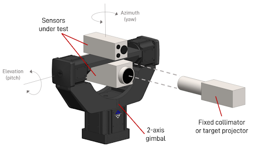
Narrow field of view (NFOV) sensors with high magnification are often used for long range surveillance, distant object recognition, tracking and targeting. NFOV pixel resolution is typically much higher than that of a WFOV sensor, so the motion system has to make significantly smaller and more precise motion to test a narrow field of view. As shown in Figure 1, NFOV and WFOV sensors can be mounted onto a gimbal to test their performance. The step sizes, accuracy, repeatability, line of sight jitter and off-axis motion errors all must be much smaller than the pixel resolution and required system error budget.
System Level Testing
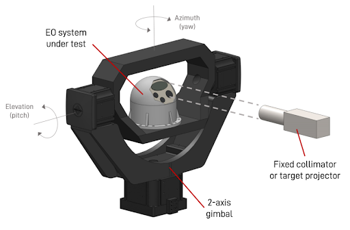
At the EO system level, the combination of EO imaging sensors, laser rangefinder/designators, control system servo gimbals/mounts/pods with inertially stabilized line of sight (LOS) pointing, image processing and object tracking systems must be tested together to verify they interact and perform correctly together. As depicted in Figure 2, an EO surveillance system can be mounted on a gimbal and tests can be run on all the passive and active EO and stabilization systems. Another system level test example would be to mount a missile seeker including its inertially guided autopilot system and run motion combined with EO tests. System level testing often requires simultaneous presentation of an EO moving target while the unit under test (UUT) is stimulated with base motion by a shaker or tilt tables to simulate vehicle base motion or flight of the UUT in real world operation. Automated EO tests with motion systems simulating target motion and base vehicle motion are key components in testing complete systems for performance and quality verification.
Fundamental Design Practices for EO Motion Test Systems
Test Motion System Angular Performance Considerations
EO system pixel resolution and pointing accuracy specs are improving as technology evolves with higher density detectors, more sensitive imagers and better signal processing. Having a highly accurate and repeatable angular positioning system that moves the target line of sight consistently with exact, uniform steps through the sensor field of view is paramount to ensuring successful EO test results. For certain tests like distortion measurements, the target must maintain the same fixed distance from the UUT as it travels to the predetermined steps, so the EO pixel resolution is the same at each location. It is important to keep the target normal to the UUT so the target symmetry and size perspective are the same at each location. When testing image processing/tracking systems, the target size, perspective and obscurations will be varied to confirm the tracking algorithms can adapt to a changing target.
Test Design Rules of Thumb
When designing an EO test system, follow these motion system fundamentals for the best possible test outcome:
- Minimize axes count and keep the motion as close as possible to the UUT. Keeping the motion axes count and stacked stage number down will make the system more accurate and result in less overall jitter. Adding more motion axes in the line of sight will add other sources of position error, bearing errors and energy/jitter that must be considered.
- Attempt to have motion specifications be 1/10th of the pixel resolution size of the UUT specs. Keep motion accuracy, repeatability, min step size and jitter to less than the pixel size for good test results. The motion system must be able to move and settle to a smaller level than the resolution of the sensor being tested, otherwise image blur can occur.
- High fundamental encoder (HFE) resolution in the motion actuators is important to minimize test equipment position and jitter. Stationary image analysis tests or moving line of sight tests have less jitter and better accuracy, repeatability and stepping with HFE resolution.
- The test bed should be a rigid, vibration-isolated mounting surface for the equipment. Base vibration, poor flatness, poor stiffness or separation of the UUT and test equipment mounting surfaces can adversely affect precise measurements. When a heavy motion test system moves, it can tilt or flex its mounting surface. Always consider the base stiffness relative to possible deflections from the moving mass, and note that the mounting surface deflections and stiffness need to be checked against EO test requirements. Optical tables provide vibration isolation and common mounting holes, but their flatness is not as good as a well-lapped granite surface. Optical tables can flex under high load movement and cause test equipment line of sight errors. Mounting surface flatness can affect a motion system’s bearing linear and angular performance, so care must be taken to ensure the mounting surface flatness errors do not significantly affect the motion system performance relative to the precision needed to test the EO sensor.
Test Layout Decisions
The first test layout consideration should be whether to move the UUT or the test equipment. Physical size and constraints of the UUT, test equipment and test layout often dictate which item should be moved. If the UUT or test equipment is extremely large or has many hoses, cables or other elements that cannot be moved or need high force or torque to bend, it is not a good candidate for moving. If possible, the smaller, less encumbered item should be considered the moving unit. The larger the moving object is, the larger and more expensive the motion system will be.
These issues drive the test design to one of three typical layouts: moving the UUT with fixed test equipment, steering the image line of sight between the UUT and test equipment with a mirror gimbal, and moving the test equipment with a fixed UUT.
Moving UUT, Fixed Test Equipment Layout
Moving the UUT puts the least amount of test equipment error close to the focal point of the sensor. Figures 1 and 2 show examples where WFOV/NFOV sensors and full EO systems can be moved while viewing EO test equipment such as the target collimator shown. Mounting a UUT on a two-axis gimbal can provide a vertical test angle of roughly -60 degrees to +135 degrees and horizontal field of view test angles close to +/-80 degrees before the sensor line of sight is blocked by the gimbal. If a goniometer can be used for the upper gimbal axis, the UUT can be tested in 360 degrees horizontally, but the vertical angle may only be +/-45 degrees or less. Error motions of the rotational axes have a small effect on the overall test accuracy in this layout since the EO focal point is centered on the gimbal axes. If the gimbal bearing tilt error motions can be kept to sensor sub-pixel levels and the axes’ linear geometric errors to less than one pixel, this configuration will provide very small test equipment line of sight error. Aligning the UUT and gimbal coordinate systems is important, and line of sight cross talk from the gimbal axes’ orthogonality and mounting issues should be checked with a camera looking at a target and sweeping the gimbal horizontally in azimuth while capturing a target’s image location vertically without moving the elevation axis. Most motion controllers have error correction capabilities, allowing orthogonality errors to be automatically corrected by the controller interpolating an azimuth-to-elevation orthogonality lookup table.
These points keep test equipment motion errors at a minimum, so any UUT line of sight measurements are truly due to the imager seeing through the optics.
Steering the Line of Sight Between UUT and Test Equipment Layout
A somewhat simpler and highly accurate way to test an EO system is to put a mirror gimbal near the EO sensor to move the UUT line of sight relative to the test target and precisely steer the line of sight between the UUT and the test equipment, as shown in Figure 3. This eliminates having to mount the EO system to the motion system and dealing with EO system cables, hoses and other elements on the motion system. The mirror must be large enough to steer the line of sight image diameter on its face (instead of moving the UUT or test equipment, as discussed in the other two test layouts). Test designers need to remember if the mirror gimbal is 45 degrees off axis in azimuth, the UUT image diameter is double its size compared to when the gimbal was at 0 degrees. The mirror gimbal’s physical travel only needs to be half of the sensor’s total FOV angle because reflecting the image angle at the gimbal doubles the image angle between the EO sensor and the test equipment. Before ordering equipment, the test’s full angular image path should be simulated with a ray trace diagram to make sure it covers the sensor FOV without any part of the gimbal vignetting the image. 3D modelling is an effective tool to look for optical image interference and verify that the test layout has full field of view capability.
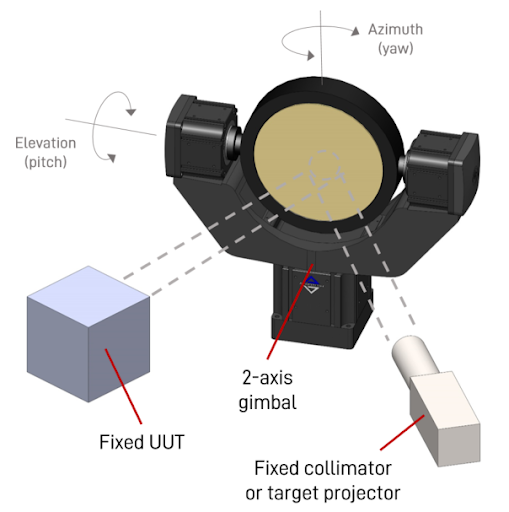
If the imager is in a vacuum chamber, it may be necessary to have the photonics test equipment outside the chamber. Using a mirror gimbal to reflect the target line of sight through the vacuum chamber window to the UUT in the chamber is an effective way to keep the non-vacuum rated equipment outside the chamber. Refractive index changes and window distortion on the line of sight can be measured and removed from the test data. If these errors cannot be practically removed, the target and mirror gimbal may need to be put into the vacuum chamber. Using a mirror gimbal with medium to high bandwidth is also a good way to simulate operational sensing and tracking tests of moving targets with the EO system. It’s also a simpler, more affordable solution because the UUT’s and test equipment’s mechanical and electrical interfaces do not need to be moved.
Fixed UUT, Moving Target Test Layout
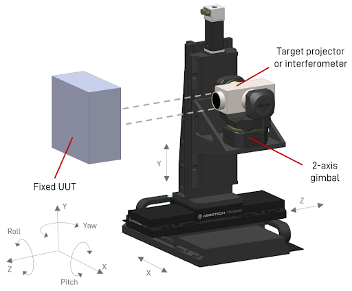
This test layout, shown in Figure 4, is a good idea if the EO sensor is very large, heavy or has characteristics that make it impossible to move during the test. Moving the test equipment angularly around a UUT sensor FOV can make the control program complicated, especially if the sensor has a WFOV. To point a target projector or interferometer around a EO sensor FOV would require moving it on a hemisphere centered on the sensor and a five- or six-axis motion system. With a small field of view EO sensor (e.g. 0.5 to 10 degrees) it is possible to do this type of test effectively with a hexapod on XZ stages for pitch and yaw motion about the hemisphere space. An example of a system built for this test is shown in Figure 5.
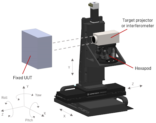
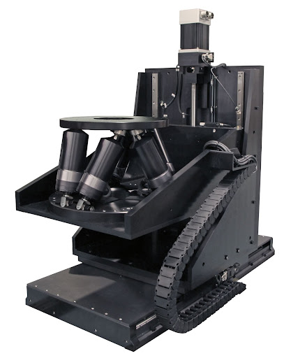
If roll is also needed, a Y linear stage would be needed to combine with the roll motion of the hexapod. If the focal distance and/or sensor FOV are large, the hexapod may not have enough travel to cover the sensor FOV by itself. The hexapod can also be used to correct for geometric error motions of the linear stages that result in line of sight errors.
An XYZ with gimbal solution, as shown in Figure 6, can perform similar motion to the XYZ with hexapod solution. The XYZ with gimbal approach allows considerably more angular motion than the hexapod solution, so it’s better suited for a WFOV sensor application. However, this solution has limitations in field of view due to packaging and axis layout.
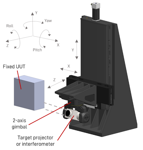
The layout in Figure 7 shows an inverted gimbal on an X, Y and Z linear stage carrying a target projector. If the target projector has to move well below the UUT to cover a large field of view, inverting the gimbal and target projector is a more optimal arrangement. A similar arrangement that replaces the gimbal with an inverted hexapod can be used to provide small motion and error correction capabilities.
Summary
This paper summarizes the various test arrangements and layouts used in testing EO systems. As with most engineering decisions, there are tradeoffs that must be weighed as part of the system design.