Application Note, Optics & Photonics
Application Note
Part-Speed Position Synchronized Output
Part-Speed Position Synchronized Output (PSO) is an effective tracking mode for Aerotech’s PSO advanced controller feature. Part-Speed PSO commands high-speed, low-latency output pulses based on the commanded vector velocity.
Extending PSO Capabilities
Aerotech’s PSO controller feature has long been used by industrial and research users alike to command their process tool – a laser, sensor, camera or other device – at very high repetition rates and with extremely low latencies. The seamless integration of process and motion control is one of the factors that make Aerotech’s controllers highly desirable.
PSO normally requires direct access to up to three axes of encoder feedback in order to calculate the vector distance traveled. Requiring access to real position has its benefits but has also been a limiting factor in the adoption of PSO for some applications. Due to the sum of the squares equation used to calculate the spacing of PSO firing events, traditional X/Y/Z Cartesian systems were required to use PSO.
Part-Speed PSO enables the user to access PSO capabilities even when encoder feedback is nonlinear or not accessible. With Aerotech’s Automation1 controller and Part-Speed PSO, control of the PSO output can be based on the velocity command of your process tool with respect to the part being processed. This capability enables PSO to be used in several new situations, such as:
1. The part-space (programming) coordinate space is not identical to the machine-space (motion axes) coordinate space. This can occur for reasons such as:
- The X/Y/Z position command is modified by a kinematic transformation (4-axis systems, 5-axis systems, 3-axis galvo scanners, hexapods, etc.).
- Tool normalcy is achieved via a rotation axis.
- A linear move is achieved by using nonlinear axes. (Figure 1 depicts a system in which motion in the Y direction may be achieved by translating the Y axis and also by rotating the A axis).
2. The type of encoder feedback required for the PSO hardware circuit is not accessible. This can occur because:
- Non-compatible PSO feedback devices are being used (absolute encoders).
- Desired reduction in wiring complexity.


Programming Part-Speed PSO
The following programming example uses these axis configurations:
- X and Y are virtual axes within the work space.
- x is a real axis (in other words, an actual drive connected to the Automation1 controller network).
Also note that x may not be the only real axis being commanded. However, it is the axis that contains the physical PSO output and hardware.
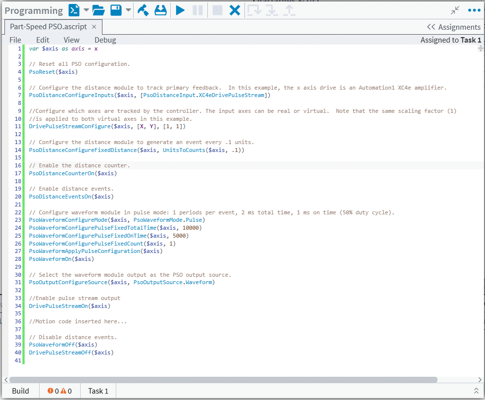
Part-Speed PSO is configured by extending the use of pre-existing Automation1 commands:
- The PsoDistanceConfigureInputs may be configured to track distance based on an internal pulse generator.
- Pulses are generated based on the axis inputs declared in the DrivePulseStreamConfigure function.
The DrivePulseStreamConfigure function is used to establish which axes will be used to generate the tracked velocity command, which is subsequently calculated using the square root of the sum of squares of the components of each axis specified. In the example program, virtual axes X and Y are tracked. The PsoDistanceConfigureInputs function is also used to determine which real drive will receive the velocity command. In this example, it is the “real” x axis. For that reason, the “real” x axis is the axis that receives all of the PSO commands, including the PsoDistanceConfigureInputs function.
Example Program Setting Up Part-Speed PSO


Another recent Aerotech white paper, Customized Relationships and Coordinated Motion with StatusGetAxisItemFast(), discussed how the Automation1 controller allows for advanced kinematic relationships to be quickly implemented. Although not thoroughly discussed in this particular white paper, pairing together a kinematic program (often running on a separate controller programming “task”) with Part-Speed PSO demonstrates the most advanced implementation of this new controller feature. As you program to virtual axes and use the commanded vector velocity of virtual axes as the input to the PsoDistanceConfigureInputs function, the separate kinematic program commands the real axes to effectively move your work point as you have commanded the virtual axes.
Technical Considerations
The following should be considered when implementing Part-Speed PSO.
First, the DrivePulseStreamOn function pulse generator output is limited to a 95 MHz output rate. The CountsPerUnit parameter and programmed velocity (feed rate) of the virtual axes will determine the pulse stream data rate. The maximum allowable programmed velocity, referred to as “FeedRate,” may be determined from the equation:
FeedRate = EncoderCountFreq/CountsPerUnit
where EncoderCountFreq = 95 MHz.
Second, the CountsPerUnit parameter should be chosen such that the resolution of the virtual axes in the work space is smaller than the PsoDistanceConfigureFixedDistance specified within the program configuration (reference line 14 in the example code).
Third, the PSO outputs on Aerotech drives have an output frequency limit for PSO output pulses. Using the referenced frequency limit, the minimum spacing between pulses can be determined from the equation:
MinSpacing = FeedRate/LaserOutputFreq
where LaserOutputFreq is the value determined from the applicable drive hardware manual.
