Ensemble Epaq MR Stand-Alone Controller and Drive Rack
Nicht empfohlen für neue Designs. Siehe die neue Automation1-iXR3. Der Ensemble® Epaq MR ist Aerotechs Stand-Alone-Controller für Anwendungen mit mittlerer bis hoher Leistung. Sie bietet eine Funktionalität, die für Anwendungen von grundlegenden Laborexperimenten und allgemeiner Positionierung bis hin zu fortschrittlichen OEM-Systemen zu einem erschwinglichen Preis geeignet ist. Der Ensemble Epaq MR wird in einer 4- oder 8-achsigen 3U-Rackmount-Version angeboten.
Description
Specifications
Dimensions
Ordering Info
Downloads
Description
Description
Specifications
Dimensions
Ordering Info
Downloads
Description
Design-Merkmale
- Bis zu sechs integrierte Antriebe in einer Stand-alone-Steuerung
- Zusätzliche externe Antriebsachsen können hinzugefügt werden, um bis zu neun Achsen mit koordinierter Bewegung zu ermöglichen
- Controller-Architektur, die die Bewegung von bis zu fünf unabhängigen Aufgaben koordinieren kann
- Fähig zum Antrieb und zur Steuerung von linearen oder rotierenden bürstenlosen, DC-Bürsten-Servomotoren und Mikro-Schrittmotoren
- Komplette Bewegungsfunktionen: Punkt-zu-Punkt, lineare und zirkuläre Interpolation, elektronisches Getriebe, Geschwindigkeitsprofilierung
- Programmieren in AeroBasic mit der IDE, Microsoft .NET einschließlich C#, VB.NET, C++/CLI, LabVIEW und MATLAB
- Ferngesteuerte ASCII-Schnittstelle für Windows- oder Nicht-Windows-Programme (einschließlich Linux) zur Steuerung des Epaq über Standard-Ethernet oder RS-232-Port
- Erweiterte Windows-basierte Ferndiagnose-, Tuning- und Programmierschnittstellen-Software
- Frontpanel-Display und Steuerkreuz für komfortable menügeführte Achsensteuerung und Statusüberprüfung
- Achs-Jogging/Steuerung mit optionalem Joystick
- CE-geprüft, NRTL-Sicherheitszertifizierung, EU 2015/863 RoHS 3-Richtlinie
- Vollständig kompatibel mit den EPICS-Softwaretools und -Anwendungen, wodurch Ensemble ideal für den Einsatz in Synchrotron- und allgemeinen Laboreinrichtungen geeignet ist
- Allen-Bradley EtherNet/IP-Schnittstelle bietet volle Integration mit Ensemble; programmieren Sie das Ensemble direkt von RSLogix 5000 aus
Vielseitige, eigenständige Mehrachsensteuerung
Das Ensemble Epaq wird als 6-achsige Tischversion (Rack-Montage optional) mit Display und Jog-Pad angeboten. Sie enthält integrierte Stromversorgungen und steckbare Motor- und IO-Anschlüsse. Es werden PWM-Verstärker zur Steuerung von bürstenbehafteten, bürstenlosen und Schrittmotoren angeboten. Für Anwendungen mit hoher Leistung und geringem Rauschen sind auch Linearverstärker erhältlich. Externe Verstärker mit höherer Leistung können über die serielle Hochgeschwindigkeitsschnittstelle AeroNet an den Epaq angeschlossen werden, so dass insgesamt neun Achsen koordiniert bewegt werden können.
Dieser flexible Konfigurationsstil erlaubt es dem Anwender, verschiedene Antriebstypen (linear versus PWM, bürstenlos oder bürstenbehaftet, Schrittmotor, etc.) innerhalb desselben Positioniersystems unter Verwendung einer gemeinsamen Programmier- und Steuerungsplattform nahtlos zu kombinieren.
Mehrere Epaqs können von einem Windows®-PC über Ethernet oder USB gesteuert werden. Die optionale On-Board-Encoder-Interpolation bietet dem Anwender eine programmierbare Achsenauflösung (unter Annahme eines Sinus-Encoder-Eingangssignals), einschließlich der Möglichkeit, die Interpolationswerte (Multiplikation) per Software zu ändern.
Mächtige und intuitive Programmierfunktionalität
Mehrfache AchsensteuerungIm Gegensatz zu den meisten Controllern auf dem Markt ist es nicht notwendig, einen kryptischen Befehlssatz zu verstehen, um Bewegungen zu erzeugen. Die intuitive Benutzeroberfläche ermöglicht es dem Anwender, sofort mit der Programmierung zu beginnen. Die Online-Hilfe von Ensemble vereinfacht das Schreiben von Bewegungsprogrammen zusätzlich und enthält viele funktionale Beispiele, die leicht für Kundenanwendungen modifiziert werden können.
Die Software Ensemble mit integrierter Entwicklungsumgebung bietet eine grafische Benutzeroberfläche unter Windows®, die einen intuitiven Programmeditor, ein Fenster für die Variablenausgabe, ein Fenster für die Compilerausgabe und einen Task-Status-Monitor umfasst. Mit dieser Oberfläche kann der Anwender alle Aspekte seines Positioniersystems, egal wie komplex, einfach überwachen. Die Achsensteuerungs- und Diagnosebildschirme werden außerdem durch ein voll funktionsfähiges Autotuning-Dienstprogramm ergänzt, das die Startzeit minimiert und eine einfache Optimierung der Bewegungsachsen ermöglicht. Systemdiagnosen lassen sich einfach über die Schnittstelle ablesen. Das Windows-basierte Remote-Softwarepaket ist im Lieferumfang jedes Geräts enthalten und ermöglicht dem Benutzer das Hoch- und Herunterladen von Programmen, das Ändern von Parameterdateien und das Analysieren von Bewegungen mit dem fortschrittlichen grafischen Tuning-Paket von Aerotech, alles bequem von einem Remote-PC aus.
Ob im Stand-alone-Modus über die Frontplatte oder per Fernsteuerung über Ethernet oder USB, die volle Funktionalität des Ensemble Epaq ist verfügbar. Integrierte Konfigurations- und Überwachungsprogramme vereinfachen die Fernkommunikation. Um eine einfache serielle Verbindung und eine einfache Bedienung zu ermöglichen, verfügt der Epaq über einen RS-232-Anschluss (ein zusätzlicher RS-232-Anschluss ist optional erhältlich).
Erweiterte DSP-Steuerung
Der Ensemble Epaq nutzt die Rechenleistung mehrerer Fließkomma-DSPs mit doppelter Genauigkeit, um eine außergewöhnliche Leistung in einer Vielzahl von Anwendungen zu bieten, einschließlich Punkt-zu-Punkt-Bewegungen, Linear- und Kreisinterpolation, Einzel- und Mehrachsen-Fehlerkorrektur, direkte Kommutierung von linearen und rotierenden bürstenlosen Servomotoren und On-Board-Servo-Autotuning. Hochgeschwindigkeits-Interrupts und Datenlogging-Funktionen bieten eine Echtzeit-Verbindung zu externen Systemen. Der Ensemble Epaq bietet außerdem eine Hochgeschwindigkeits-Positionsverriegelung und eine optionale einachsige PSO-Funktion (Position Synchronized Output). Ganz gleich, ob es sich um eine einfache Punkt-zu-Punkt-Bewegung oder um komplexe Geschwindigkeitsprofile mit ""on the fly""-Ausgabe handelt, Ensemble gewährleistet Spitzenleistung für kritische Anwendungen.
Integralantriebe
Bürstenlose Servo-, DC-Bürstenservo- und Mikroschrittantriebe sind in den kompakten Rahmen des Ensemble Epaq integriert. Der Epaq kann eine beliebige Kombination von bis zu sechs integrierten Antrieben steuern, während die Ensemble-Architektur eine weitere Erweiterung (mit externen Stand-alone-Einzelachsen-Antriebseinheiten) auf insgesamt bis zu neun Achsen zulässt. Da der Epaq viele verschiedene Motortypen steuern kann, haben Kunden eine ausgezeichnete Flexibilität bei ihren Systemdesigns. Luftgelagerte Linearmotoren mit hoher Genauigkeit können vom selben Controller gesteuert werden, der auch Antriebe mit geringerer Präzision mit Servo- oder Schrittmotoren betreibt. Die Parameter lassen sich für diese verschiedenen Motoren und Rückführgeräte leicht umkonfigurieren, so dass sich die Kunden an wechselnde Systemanforderungen anpassen können.
Erweiterte Eingangs-/Ausgangsmöglichkeiten
Jeder Epaq verfügt über einen optionalen zweiten RS-232-Anschluss und einen Achsenerweiterungsanschluss. Pro Achse bietet der Epaq außerdem ein optionales E/A-Paket mit acht digitalen Ein- und Ausgängen, einem 12-Bit-Analogeingang (±10 VDC), einem 16-Bit-Ausgang (±5 VDC), einem konfigurierbaren Bremsenausgang, einem zweiten TTL-Encoder-Eingang für die Zweikreissteuerung und entweder einem zweiten Marker-Eingang oder PSO-Ausgang. Dieses optionale E/A-Paket kann zu jeder Achse hinzugefügt werden, so dass zahlreiche E/A an den Epaq angeschlossen werden können.
Erweiterung eines erfolgreichen Erbes
Obwohl Ensemble als universell einsetzbare, eigenständige Steuerung konzipiert ist, führt sie die Erfolgsgeschichte der äußerst erfolgreichen A3200- und Soloist™-Steuerungen von Aerotech fort. Sie bietet erweiterte Funktionen, die sie zu einer idealen Wahl für viele aggressive Motion-Control-Anwendungen machen. Die Ensemble-Bewegungssteuerungsarchitektur baut auf der intuitiven grafischen Benutzeroberfläche des Soloist auf und bietet gleichzeitig erweiterte Funktionen, die für die Steuerung mehrerer Achsen geeignet sind. Vorcodierte LabVIEW®-VIs, AeroBasic™-Programmierfunktionalität, MATLAB®-Bibliothek, .NET-Tools für C#, VB.NET und C++/CLI oder C machen die Bedienung des Ensemble noch einfacher. Auf der Ensemble Control-Homepage finden Sie detaillierte Informationen zu den Software-Funktionen und Bestellmöglichkeiten.
Allen-Bradley-Schnittstelle
Kombinieren Sie eine bewährte SPS mit einer bewährten Bewegungssteuerung für eine einfachere Integration, Inbetriebnahme und Wartung von mittleren und anspruchsvollen Automatisierungsprojekten. Mit der Aerotech EtherNet/IP™-Schnittstelle können AB-SPSen (MicroLogix, CompactLogix™ oder ControlLogix) direkt in das Ensemble integriert werden. Bewegungen können direkt in der RSLogix 5000-Umgebung programmiert werden oder es können separate Programme auf der Steuerung geschrieben und von der AB-SPS ausgelöst werden. Aerotech verfügt über zwei Schnittstellen: ASCII und Register. Wählen Sie die SPS, den Motion-Controller und die Schnittstelle, die am besten zu Ihren Anwendungsanforderungen passt.
EPICS-Treiber
Jede Ensemble-Installation beinhaltet volle Kompatibilität mit dem verteilten Open-Source-Steuerungssystem EPICS. EPICS wird weltweit an führenden Lichtquellen (Synchrotron) und in anderen staatlichen Laboratorien eingesetzt, so dass sich Ensemble nahtlos in Anwendungen aller großen Forschungseinrichtungen integrieren lässt.
Feature |
Units |
Description |
| Number of Axes | 1 to 8 | |
| Encoder Inputs | 1 Primary and 1 Auxiliary Per Axis | |
| Motor Style | Brush, Brushless, Stepper | |
| Power Supply | VAC | 100-240 VAC; 50/60 Hz (Factory Configured) |
| Bus Voltage | VDC | 10-80 |
| Peak Output Current (1 sec)(1) | Apk | 10 |
| Continuous Output Current(1) | Apk | 5 |
| Digital Inputs | No | |
| Digital Outputs | No | |
| Analog Inputs | One 16-bit Analog Input per Axis | |
| Analog Outputs | No | |
| Dedicated Axis I/O on Feedback Connector | Three Limit Inputs (CW, CCW, Home); Three Hall Effect Inputs (A, B, C); Three High-Speed Differential Inputs (sin, cos, mkr for encoder); Motor Over-Temperature Input; One 16-bit Analog Input | |
| Dedicated I/O on Auxiliary Feedback Connector | sin, cos, mkr for Aux Enc; Aux Enc can be used for PSO Output | |
| I/O Expansion Board(2) | One 12-bit Differential Analog Input; One 16-bit Analog Output; Eight Digital Inputs, Optically Isolated, Sinking or Sourcing; Eight Optically Isolated Digital Outputs per Axis | |
| High Speed Data Capture | Yes(2) | |
| High Speed Digital Outputs | No | |
| Bidirectional Lines | No | |
| Automatic Brake Control | Optional | |
| Emergency Stop (ESTOP) | Optional | |
| Position Synchronized Output (PSO) | Single Axis Standard | |
| Can Output Multiplied Encoder | Yes (only with MXH option) | |
| Can Output Square Wave Encoder | Yes | |
| Primary Encoder Input Frequency with Multiplication | 200 kHz (MXU) or 450 kHz (MXH) sine wave | |
| Primary Encoder Input Frequency Square Wave | 10 MHz square wave frequency/40 MHz count rate | |
| Secondary Encoder Input Frequency | 10 MHz square wave frequency/40 MHz count rate | |
| Laser Feedback Support | No | |
| Encoder Multiplication(3) | x4096 (MXU); x65536 (MXH) | |
| Resolver Interface | No | |
| Internal Shunt Resistor | No | |
| External Shunt | No | |
| Ethernet | Yes | |
| USB | No | |
| RS-232 | Yes | |
| FireWire | No | |
| Fieldbus | Modbus TCP on PC | |
| Joystick | Yes | |
| Additional Interfaces | 10/100 Base T Ethernet communication interface for system setup, application networking, Epaq-to-Epaq communications, embedded programming, immediate commands, and Modbus over TCP; USB communication interface for system setup, application networking, Windows® PC control interface; RS-232 port with programmable baud rate, length, parity, stop bits | |
| Other I/O | No | |
| Current Loop Update Rate | kHz | 20 |
| Servo Loop Update Rate | kHz | 1 to 20 |
| Power Amplifier Bandwidth | kHz | Selectable Through Software |
| Minimum Load Inductance | mH | 0.1 mH with PWM; 0 with Linear |
| Operating Temperature | °C | 0 to 50 |
| Storage Temperature | °C | -30 to 85 |
| Weight | kg (lb) | 16 (35) |
| Package | Rack Mount | |
| Compliance | CE approved, NRTL safety certification, EU 2015/863 RoHS 3 directive |
Integrated Amplifier Electrical Specifications |
MP |
ML |
|
| Output Voltage | VDC | 10, 20, 30, 40, 80 | 10, 20, 30, 40 |
| Peak Output Current | A | 10 | 10(1) |
| Continuous Output Current | A | 5 | 5(1) |
| PWM Switching Frequency | kHz | 20 | N/A |
| Power Amplifier Bandwidth | kHz | Software Selectable | Software Selectable |
| Minimum Load Inductance | mH | 0.1 | 0 |
| Operating Temperature | °C | 0 to 50 | 0 to 50 |
| Storage Temperature | °C | -20 to 85 | -20 to 85 |
| Weight | kg | 0.5 | 0.5 |
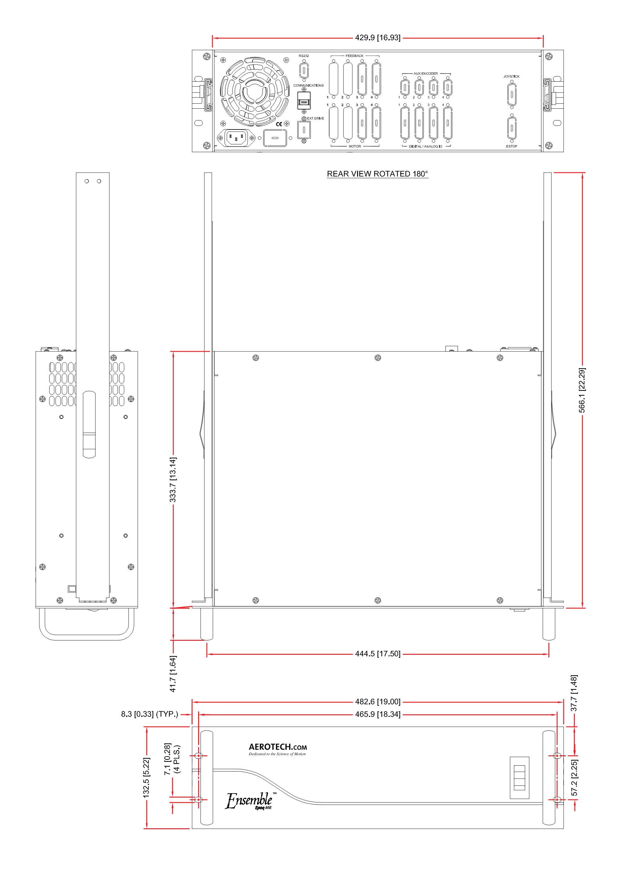
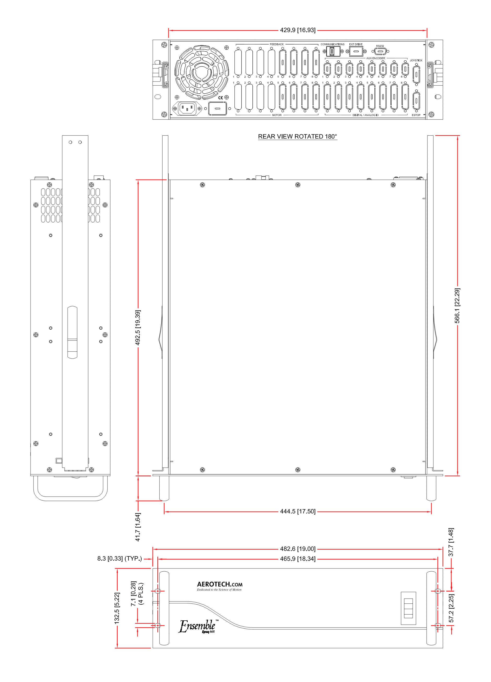
Dimensions
Ensemble Epaq MR, 4-Axis Chassis
Ensemble Epaq MR, 8-Axis Chassis
Ordering Information
Ensemble Epaq MR Software
| Option | Description |
| ENSEMBLE-MC | ENSEMBLE: Full installation of Ensemble controller and selected software components on a new system. Full part number includes software options listed below. Pricing is summation of selected software products. Maintenance (software update) included in price for one year from date of purchase. |
| -MC | MOTION COMPOSER STANDARD: Includes the Integrated Development Environment, Scope, System Diagnostics and System Maintenance. Ensemble Motion Composer is intended for deployment on desktop or industrial PC with a minimum Intel Pentium 4 processor, 512 MB RAM, Windows® XP or Windows® Vista Business (without SP1 installed). A full list of PC requirements and recommendations is available at aerotech.com. Includes the following software options: |
License
| Option | Description |
| -MACHINE | Provides the ability to write, compile, execute, debug programs in AeroBasic; full access to .NET 2.0 and C Library; access full diagnostics, fault and status information; access and set I/O, registers and variables; collect, analyze and save data; view files from machine for analysis and record keeping; connect PC to machine through Ethernet TCP/IP; upgrades can be installed (firmware or controller) using Loader; includes Ensemble-MC Standard; Note: The price of the first MACHINE license is included in the hardware price. The list price of the MACHINE license is used for multiple license copies and/or computing the Maintenance Price. |
Controller Options
| Option | Description |
| -FIVE AXIS CONTOURING | More than 4 axes of coordinated motion with a single motion command |
| -DYNAMIC CONTROLS TOOLBOX | Includes Harmonic Cancellation |
| -ENHANCED THROUGHPUT MODULE | Includes setup and monitoring screens of the ETM module; included in the price of the hardware modules sold separately |
| -LCK | Locked drive; firmware and calibration data on the drive cannot be modified by the user after the product leaves Aerotech; the drive must be returned to Aerotech if firmware/calibration updates are required; read/write access to parameters and programs is supported |
System Options
| Option | Description |
| -ETHERNET/IP | ODVA certified EtherNet/IP™ module provides full integration with Allen Bradley PLC and programmable from RSLogix. Module has two APIs: ASCII and Register-to-Register |
Motion Composer (MC) Options
| Option | Description |
| -MOTION DESIGNER | The Motion Designer is an add-on software component to the Digital Scope that provides the ability to create, import, run and evaluate motion profiles (trajectories) |
| -LABVIEW | Includes LabVIEW 8.2 VI samples |
Maintenance
| Option | Description |
| -MAINTENANCE | First year of maintenance is included with the initial purchase; additional years can be purchased |
Epaq MR Ordering Information
| Option | Description |
| Epaq MR | Four or eight axis, rack mount, stand-alone motion controller with integrated power supplies and servo/stepping motor amplifiers. Features include independent or coordinated motion, point to point, linear and circular interpolation, constant velocity, velocity profiled, time based, freerun motion types, electronic gearing, backlash compensation, and 1D or 2D axis calibration. Ensemble Standard HMI Multi-Axis Software included. Up to 10 kHz servo update rate for all axes Digital servo loop One 10/100 base T Ethernet port; one RS-232 port Dedicated I/O per axis includes: CW, CCW, and home limits, marker, Hall effect sensors, enable, fault, for each axis User-defined I/O on I/O option board includes eight opto-isolated inputs (sinking or sourcing), eight outputs (sinking or sourcing ), one 12-bit analog input, one 16-bit analog output and brake relay; this I/O is on Axis 1; optional adder for axes 2-6 |
Package
| Option | Description |
| /4AXIS-BOX | Supports up to 4 axes of motion |
| /8AXIS-BOX | Supports up to 8 axes of motion |
Line Voltage
| Option | Description |
| -A | 115 VAC input voltage |
| -B | 230 VAC input voltage |
| -C | 100 VAC input voltage |
| -D | 200 VAC input voltage |
Bus Power Supply
| Option | Description |
| -4-40LP | Four axis rack with 40 VDC bus; up to 300 watts |
| -4-80LP | Four axis rack with 80 VDC bus; up to 300 watts |
| -4-40 | Four axis rack with 40 VDC bus; up to 600 watts |
| -4-80 | Four axis rack with 80 VDC bus; up to 600 watts |
| -4-10B | Four axis rack with ±10 VDC bus; up to 400 watts |
| -4-20B | Four axis rack with ±20 VDC bus; up to 400 watts |
| -4-30B | Four axis rack with ±30 VDC bus; up to 400 watts |
| -4-40B | Four axis rack with ±40 VDC bus; up to 600 watts |
| -8-40LP | Eight axis rack with 40 VDC bus; up to 500 watts |
| -8-80LP | Eight axis rack with 80 VDC bus; up to 500 watts |
| -8-40 | Eight axis rack with 40 VDC bus; up to 500 watts |
| -8-80 | Eight axis rack with 80 VDC bus; up to 1000 watts |
| -8-10B | Eight axis rack with ±10 VDC bus; up to 400 watts |
| -8-20B | Eight axis rack with ±20 VDC bus; up to 400 watts |
| -8-30B | Eight axis rack with ±30 VDC bus; up to 400 watts |
| -8-40B | Eight axis rack with ±40 VDC bus; up to 600 watts |
Axis 1 Amplifier Options
| Option | Description |
| /1-MP10 | Digital PWM amplifier, 10 A peak, 5 A continuous |
| /1-MP10I | Digital PWM amplifier, 10 A peak, 5 A continuous with I/O option |
| /1-MP10M | Digital PWM amplifier, 10 A peak, 5 A continuous; x4096 MXU(1) |
| /1-MP10MI | Digital PWM amplifier, 10 A peak, 5 A continuous; x4096 MXU(1) with I/O option |
| /1-MP10-HB | Digital PWM amplifier, 10 A peak, 5 A continuous with half bus option |
| /1-MP10I-HB | Digital PWM amplifier, 10 A peak, 5 A continuous with I/O and half bus option |
| /1-MP10M-HB | Digital PWM amplifier, 10 A peak, 5 A continuous; x4096 MXU(1) and half bus option |
| /1-MP10MI-HB | Digital PWM amplifier, 10 A peak, 5 A continuous; x4096 MXU(1) with I/O and half bus option |
| /1-ML10 | Digital linear amplifier, 10 A peak, 5 A continuous |
| /1-ML10I | Digital linear amplifier, 10 A peak, 5 A continuous with I/O option |
| /1-ML10M | Digital linear amplifier, 10 A peak, 5 A continuous; x4096 MXU(1) |
| /1-ML10MI | Digital linear amplifier, 10 A peak, 5 A continuous; x4096 MXU(1) with I/O option |
| /1-ML10H | Digital linear amplifier, 10 A peak, 5 A continuous; x65536 MXH(1) |
| /1-ML10HI | Digital linear amplifier, 10 A peak, 5 A continuous; x65536 MXH(1) with I/O option |
- Effective multiplication factor specified after quadrature decoding (if applicable).
Axis 2 Amplifier Options
| Option | Description |
| /2-MP10 | Digital PWM amplifier, 10 A peak, 5 A continuous |
| /2-MP10I | Digital PWM amplifier, 10 A peak, 5 A continuous with I/O option |
| /2-MP10M | Digital PWM amplifier, 10 A peak, 5 A continuous; x4096 MXU(1) |
| /2-MP10MI | Digital PWM amplifier, 10 A peak, 5 A continuous; x4096 MXU(1) with I/O option |
| /2-MP10-HB | Digital PWM amplifier, 10 A peak, 5 A continuous with half bus option |
| /2-MP10I-HB | Digital PWM amplifier, 10 A peak, 5 A continuous with I/O and half bus option |
| /2-MP10M-HB | Digital PWM amplifier, 10 A peak, 5 A continuous; x4096 MXU(1) and half bus option |
| /2-MP10MI-HB | Digital PWM amplifier, 10 A peak, 5 A continuous; x4096 MXU(1) with I/O and half bus option |
| /2-ML10 | Digital linear amplifier, 10 A peak, 5 A continuous |
| /2-ML10I | Digital linear amplifier, 10 A peak, 5 A continuous with I/O option |
| /2-ML10M | Digital linear amplifier, 10 A peak, 5 A continuous; x4096 MXU(1) |
| /2-ML10MI | Digital linear amplifier, 10 A peak, 5 A continuous; x4096 MXU(1) with I/O option |
| /2-ML10H | Digital linear amplifier, 10 A peak, 5 A continuous; x65536 MXH(1) |
| /2ML10HI | Digital linear amplifier, 10 A peak, 5 A continuous; x65536 MXH(1) with I/O option |
- Effective multiplication factor specified after quadrature decoding (if applicable).
Axis 3 Amplifier Options
| Option | Description |
| /3-MP10 | Digital PWM amplifier, 10 A peak, 5 A continuous |
| /3-MP10I | Digital PWM amplifier, 10 A peak, 5 A continuous with I/O option |
| /3-MP10M | Digital PWM amplifier, 10 A peak, 5 A continuous; x4096 MXU(1) |
| /3-MP10MI | Digital PWM amplifier, 10 A peak, 5 A continuous; x4096 MXU(1) with I/O option |
| /3-MP10-HB | Digital PWM amplifier, 10 A peak, 5 A continuous with half bus option |
| /3-MP10I-HB | Digital PWM amplifier, 10 A peak, 5 A continuous with I/O and half bus option |
| /3-MP10M-HB | Digital PWM amplifier, 10 A peak, 5 A continuous; x4096 MXU(1) and half bus option |
| /3-MP10MI-HB | Digital PWM amplifier, 10 A peak, 5 A continuous; x4096 MXU(1) with I/O and half bus option |
| /3-ML10 | Digital linear amplifier, 10 A peak, 5 A continuous |
| /3-ML10I | Digital linear amplifier, 10 A peak, 5 A continuous with I/O option |
| /3-ML10M | Digital linear amplifier, 10 A peak, 5 A continuous; x4096 MXU(1) |
| /3-ML10MI | Digital linear amplifier, 10 A peak, 5 A continuous; x4096 MXU(1) with I/O option |
| /3-ML10H | Digital linear amplifier, 10 A peak, 5 A continuous; x65536 MXH(1) |
| /3-ML10HI | Digital linear amplifier, 10 A peak, 5 A continuous; x65536 MXH with I/O option |
- Effective multiplication factor specified after quadrature decoding (if applicable).
Axis 4 Amplifier Options
| Option | Description |
| /4-MP10 | Digital PWM amplifier, 10 A peak, 5 A continuous |
| /4-MP10I | Digital PWM amplifier, 10 A peak, 5 A continuous with I/O option |
| /4-MP10M | Digital PWM amplifier, 10 A peak, 5 A continuous; x4096 MXU(1) |
| /4-MP10MI | Digital PWM amplifier, 10 A peak, 5 A continuous; x4096 MXU(1) with I/O option |
| /4-MP10-HB | Digital PWM amplifier, 10 A peak, 5 A continuous with half bus option |
| /4-MP10I-HB | Digital PWM amplifier, 10 A peak, 5 A continuous with I/O and half bus option |
| /4-MP10M-HB | Digital PWM amplifier, 10 A peak, 5 A continuous; x4096 MXU(1) and half bus option |
| /4-MP10MI-HB | Digital PWM amplifier, 10 A peak, 5 A continuous; x4096 MXU(1) with I/O and half bus option |
| /4-ML10 | Digital linear amplifier, 10 A peak, 5 A continuous |
| /4-ML10I | Digital linear amplifier, 10 A peak, 5 A continuous with I/O option |
| /4-ML10M | Digital linear amplifier, 10 A peak, 5 A continuous; x4096 MXU(1) |
| /4-ML10MI | Digital linear amplifier, 10 A peak, 5 A continuous; x4096 MXU(1) with I/O option |
| /4-ML10H | Digital linear amplifier, 10 A peak, 5 A continuous; x65536 MXH(1) |
| /4-ML10HI | Digital linear amplifier, 10 A peak, 5 A continuous; x65536 MXH(1) with I/O option |
- Effective multiplication factor specified after quadrature decoding (if applicable).
Axis 5 Amplifier Options
| Option | Description |
| /5-MP10 | Digital PWM amplifier, 10 A peak, 5 A continuous |
| /5-MP10I | Digital PWM amplifier, 10 A peak, 5 A continuous with I/O option |
| /5-MP10M | Digital PWM amplifier, 10 A peak, 5 A continuous; x4096 MXU(1) |
| /5-MP10MI | Digital PWM amplifier, 10 A peak, 5 A continuous; x4096 MXU(1) with I/O option |
| /5-MP10-HB | Digital PWM amplifier, 10 A peak, 5 A continuous with half bus option |
| /5-MP10I-HB | Digital PWM amplifier, 10 A peak, 5 A continuous with I/O and half bus option |
| /5-MP10M-HB | Digital PWM amplifier, 10 A peak, 5 A continuous; x4096 MXU(1) and half bus option |
| /5-MP10MI-HB | Digital PWM amplifier, 10 A peak, 5 A continuous; x4096 MXU(1) with I/O and half bus option |
- Effective multiplication factor specified after quadrature decoding (if applicable).
Axis 6 Amplifier Options
| Option | Description |
| /6-MP10 | Digital PWM amplifier, 10 A peak, 5 A continuous |
| /6-MP10I | Digital PWM amplifier, 10 A peak, 5 A continuous with I/O option |
| /6-MP10M | Digital PWM amplifier, 10 A peak, 5 A continuous; x4096 MXU(1) |
| /6-MP10MI | Digital PWM amplifier, 10 A peak, 5 A continuous; x4096 MXU(1) with I/O option |
| /6-MP10-HB | Digital PWM amplifier, 10 A peak, 5 A continuous with half bus option |
| /6-MP10I-HB | Digital PWM amplifier, 10 A peak, 5 A continuous with I/O and half bus option |
| /6-MP10M-HB | Digital PWM amplifier, 10 A peak, 5 A continuous; x4096 MXU(1) and half bus option |
| /6-MP10MI-HB | Digital PWM amplifier, 10 A peak, 5 A continuous; x4096 MXU(1) with I/O and half bus option |
- Effective multiplication factor specified after quadrature decoding (if applicable).
Axis 7 Amplifier Options
| Option | Description |
| /7-MP10 | Digital PWM amplifier, 10 A peak, 5 A continuous |
| /7-MP10I | Digital PWM amplifier, 10 A peak, 5 A continuous with I/O option |
| /7-MP10M | Digital PWM amplifier, 10 A peak, 5 A continuous; x4096 MXU(1) |
| /7-MP10MI | Digital PWM amplifier, 10 A peak, 5 A continuous; x4096 MXU(1) with I/O option |
| /7-MP10-HB | Digital PWM amplifier, 10 A peak, 5 A continuous with half bus option |
| /7-MP10I-HB | Digital PWM amplifier, 10 A peak, 5 A continuous with I/O and half bus option |
| /7-MP10M-HB | Digital PWM amplifier, 10 A peak, 5 A continuous; x4096 MXU(1) and half bus option |
| /7-MP10MI-HB | Digital PWM amplifier, 10 A peak, 5 A continuous; x4096 MXU(1) with I/O and half bus option |
- 1. Effective multiplication factor specified after quadrature decoding (if applicable).
Axis 8 Amplifier Options
| Option | Description |
| /8-MP10 | Digital PWM amplifier, 10 A peak, 5 A continuous |
| /8-MP10I | Digital PWM amplifier, 10 A peak, 5 A continuous with I/O option |
| /8-MP10M | Digital PWM amplifier, 10 A peak, 5 A continuous; x4096 MXU(1) |
| /8-MP10MI | Digital PWM amplifier, 10 A peak, 5 A continuous; x4096 MXU(1) with I/O option |
| /8-MP10-HB | Digital PWM amplifier, 10 A peak, 5 A continuous with half bus option |
| /8-MP10I-HB | Digital PWM amplifier, 10 A peak, 5 A continuous with I/O and half bus option |
| /8-MP10M-HB | Digital PWM amplifier, 10 A peak, 5 A continuous; x4096 MXU(1) and half bus option |
| /8-MP10MI-HB | Digital PWM amplifier, 10 A peak, 5 A continuous; x4096 MXU(1) with I/O and half bus option |
- Effective multiplication factor specified after quadrature decoding (if applicable).
Line Cord (must select one)
| Option | Description |
| /ENGLAND | UK compatible line cord |
| /GERMANY | German compatible line cord |
| /ISRAEL | Israel compatible line cord |
| /INDIA | India compatible line cord |
| /AUSTRALIA | Australia compatible line cord |
| /US-115VAC | US 115 VAC line cord |
| /US-230VAC | US 230 VAC line cord |
| /NO-LINECORD | No line cord |
Brake Options (up to 4 selections allowable)
| Option | Description |
| /BRAKE-1 | Axis 1 wired for 24 V, 1 A brake |
| /BRAKE-2 | Axis 2 wired for 24 V, 1 A brake (amp must have I or MI option) |
| /BRAKE-3 | Axis 3 wired for 24 V, 1 A brake (amp must have I or MI option) |
| /BRAKE-4 | Axis 4 wired for 24 V, 1 A brake (amp must have I or MI option) |
| /BRAKE-5 | Axis 5 wired for 24 V, 1 A brake (amp must have I or MI option) |
| /BRAKE-6 | Axis 6 wired for 24 V, 1 A brake (amp must have I or MI option) |
| /BRAKE-7 | Axis 7 wired for 24 V, 1 A brake (amp must have I or MI option) |
| /BRAKE-8 | Axis 8 wired for 24 V, 1 A brake (amp must have I or MI option) |
Options (multiple selections allowable)
| Option | Description |
| -ESTOP1 | Controller stops motion, then disables servo control. Internal positive guided relay with monitor contact disconnects AC power source from motor. Operator risk assessment is the responsibility of the end user or integrator |
| -ESTOP2 | Same as ESTOP1 but uses two relays |
| -ESTOP3 | Same as ESTOP2 but contains 1 second bus discharge resistors |
| -SLIDE | Rack-mount slides |
Standard Motor Power and Combination Power/FeedBack Cables (order as separate line items)
| Option | Description |
| C21481-50 | CABLE: BL MTR-4TS-4MS-LP1-MAX450DM: MS motor power cable, Epaq 4-terminal connector to 4-pin MS connector; 5 A continuous current (5 meters long) |
| C21491-50 | CABLE: BL MTR-4TS-4DU-LP1-MAX450DM: HPD motor power cable, Epaq 4-terminal connector to 4-pin High Power D connector; 5 A continuous current (5 meters long) |
| C21511-50 | CABLE: BL MTR-4TS-4DU-LP1-HF-MAX450DM: Hi Flex HPD motor power cable, Epaq 4-terminal connector to 4-pin High Power D connector; 5 A continuous current (5 meters long) |
| C21501-50 | CABLE: BL MTR & FB-4TS-25DU-25DU-MAX107DM: 25-pin D stage to split Epaq 4-terminal strip motor power and 25D feedback cable (5 meters long) |
| C21521-50 | CABLE: SM MTR & FB-25DU-4TS-23B-MAX107DM: 23-pin stepper motor connector to split Epaq 4-terminal strip motor power and 25D feedback cable (5 meters long) |
| C22091-50 | Motor power cable, high flex, 5.0 meters long, for use with Epaq; 4 A continuous current rating; to be used with 10 A peak drives ONLY Motor type: brushless Motor/stage connector: 4-pin high power D Amplifier connector: 4-pin terminal strip Epaq connector Maximum cable length: 45 meters Minimum bend radius 60 mm (2.36") Rated for continuous flex BL MTR-FLB-4DU-HF60-4ARMS-MAX 450DM |
Integration (Required)
Aerotech offers both standard and custom integration services to help you get your system fully operational as quickly as possible. The following standard integration options are available for this system. Please consult Aerotech if you are unsure what level of integration is required, or if you desire custom integration support with your system.
| Option | Description |
| -TAS | Integration - Test as system Testing, integration, and documentation of a group of components as a complete system that will be used together (ex: drive, controller, and stage). This includes parameter file generation, system tuning, and documentation of the system configuration. |
| -TAC | Integration - Test as components Testing and integration of individual items as discrete components that ship together. This is typically used for spare parts, replacement parts, or items that will not be used together. These components may or may not be part of a larger system. |