Capability Overview, Custom Engineered Motion Systems, Hexapods, Motion Control Platforms, Optics & Photonics, Piezoelectric Nanopositioners, Precision Manufacturing, Process-Specific Products, Science & Research Institutions, Stages & Actuators, Test & Inspection
Capability Overview
Optical Alignment Algorithms
Precision motion mechanics, such as Aerotech’s FiberMaxHP and other photonic alignment platforms, are critical for enabling high-quality results and efficient throughput for photonic device testing and manufacturing. However, the hardware for these precision alignment applications is just one part of the solution; the control software optimizing motion commands also plays a key role. Purpose-built control software reduces startup time for new applications, and when combined with precision mechanics and drive electronics it improves alignment accuracy and speed to meet the quality and throughput demands of modern photonics manufacturing processes.
Aerotech’s AeroAlign optical alignment algorithms – which are compatible with any system running on the Automation1 motion control platform – are purpose-built to solve these complex photonic alignment challenges. The AeroAlign algorithms support a wide variety of kinematic configurations, including serial and parallel kinematic systems, and come equipped with a range of configurable parameters to enable optimization for your specific process. Additionally, the AeroAlign algorithms package includes signal simulation functionality that allows users to design and test their process in a virtual environment before performing real-world alignments of physical hardware. More detail on each of the AeroAlign algorithms is provided below.
AeroAlign1D
The AeroAlign1D function illustrated in Figure 1 is used to search along one degree of freedom for a local power peak or a defined power threshold. This algorithm can perform a complete scan of a defined 1D area and return to the point of maximum (or minimum) power, or it can be configured to terminate motion and remain in place upon reaching a user-defined power threshold.


AeroAlignSpiral
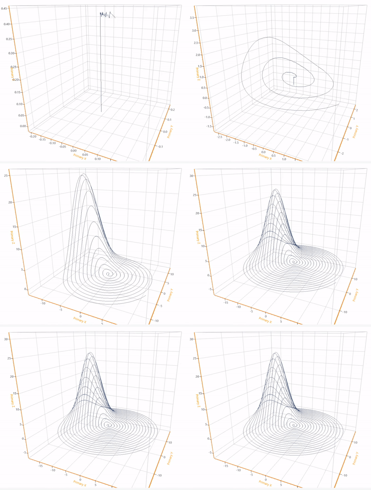
The AeroAlignSpiral function is used to search along two degrees of freedom for a local power peak or a defined power threshold. As shown in Figure 2, this algorithm can perform a complete scan of a defined circular 2D area and return to the point of maximum (or minimum) power, or it can be configured to terminate motion and remain in place upon reaching a user-defined power threshold.


AeroAlignDynamic
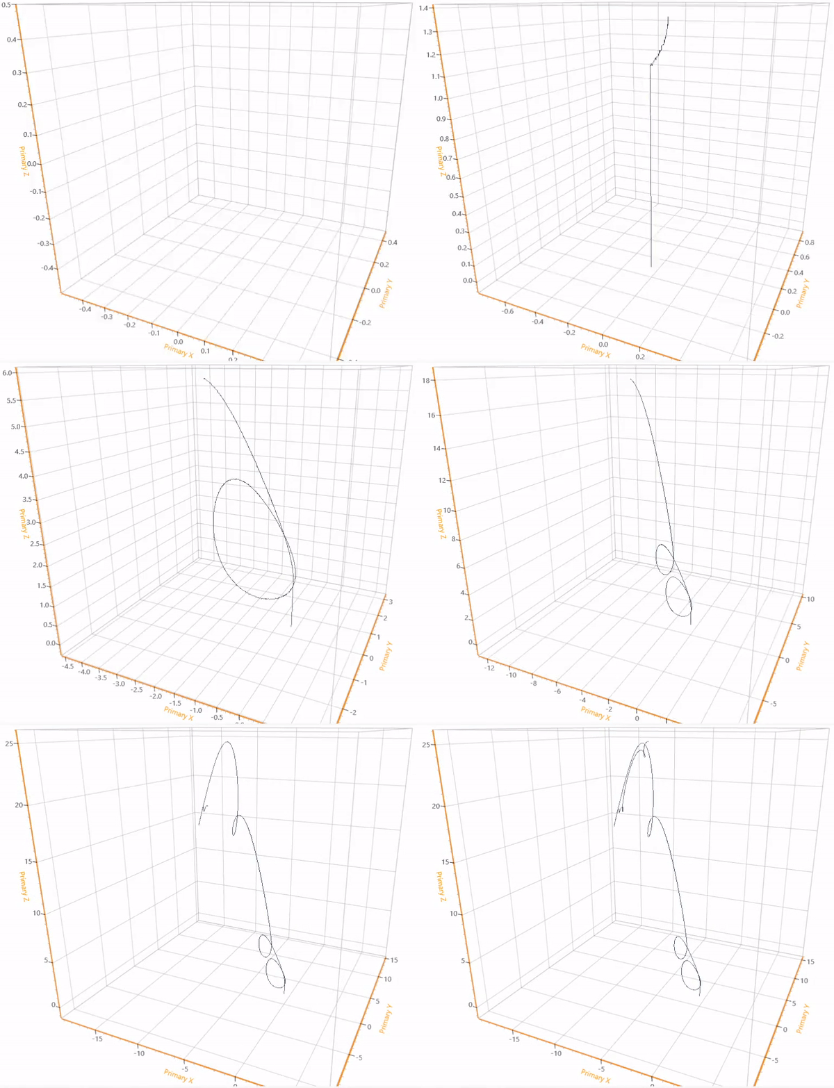
The AeroAlignDynamic function is used in one of two ways: it can optimize the position of two degrees of freedom to find a power peak, or it can dynamically track the position of an existing peak. AeroAlignDynamic requires an optical signal (first light) to initiate. After first light is identified, AeroAlignDynamic climbs a local power peak and then either stops when a user-defined threshold is reached or continues to track the movement of that peak until the end of a user-defined time period. This is illustrated in Figure 3.


AeroAlignFast
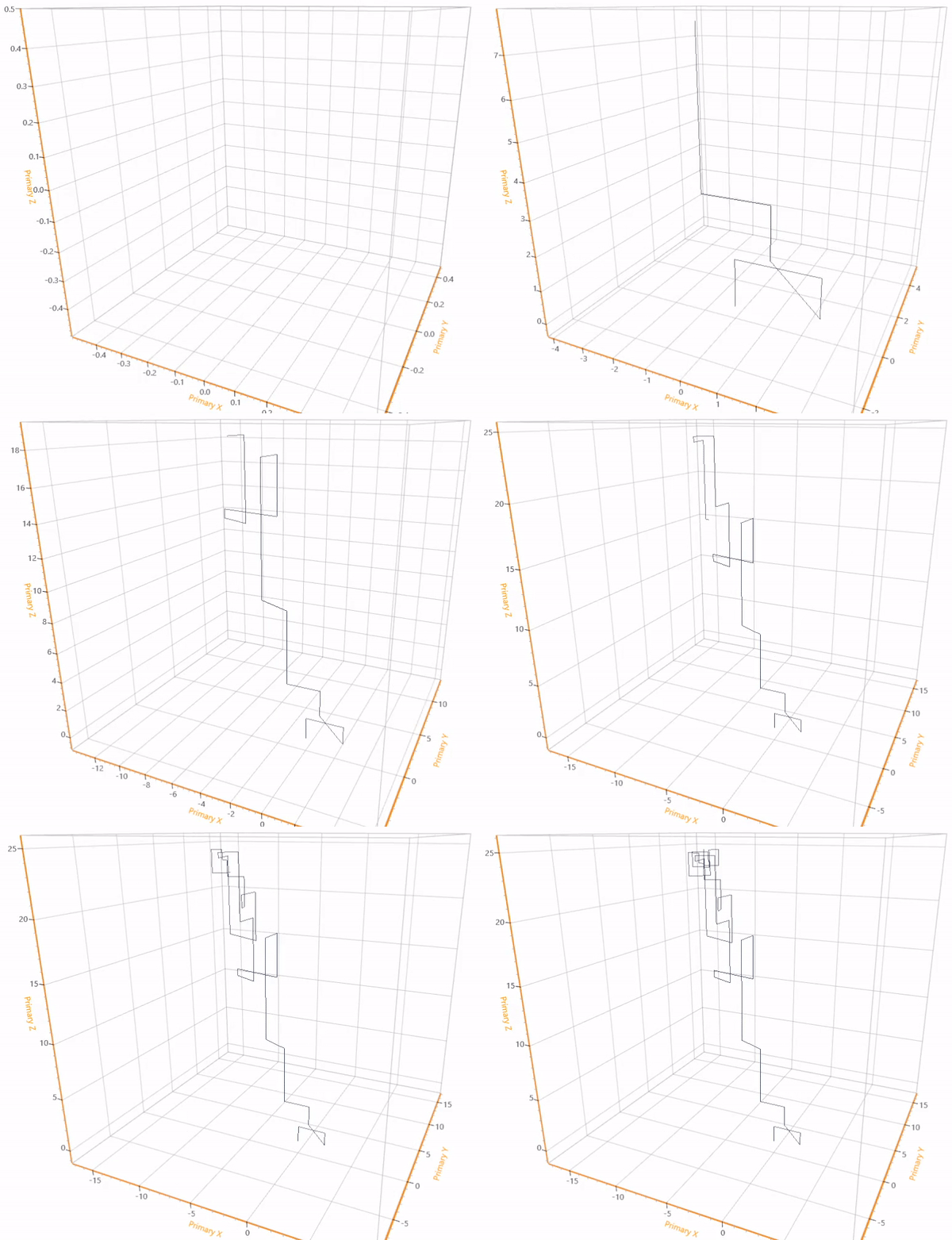
The AeroAlignFast function, shown in Figure 4, uses an iterative search routine to identify a position where the power signal exceeds a user-defined threshold. This algorithm supports up to six degrees of freedom and can be used in a wide range of kinematic configurations, including across multiple alignment platforms. AeroAlignFast requires an optical signal (first light) to initiate.


Which Algorithm Do I Use?
The AeroAlign optical alignment algorithms address a wide variety of alignment processes in both R&D and high-volume manufacturing environments. Depending on the application goals, alignment tolerances, throughput requirements and other considerations, different algorithms (or combinations of algorithms) may be more suitable for a given process. For example, both AeroAlignDynamic and AeroAlignFast require an optical signal (often called first light) to initiate. If the alignment search is starting without a signal, users can deploy AeroAlign1D or AeroAlignSpiral to establish a signal and then use AeroAlignFast or AeroAlignDynamic to optimize the alignment. The AeroAlign algorithms can even be combined with Tool Center Point Programming (another AeroScriptPlus feature) to perform complex alignments of multi-channel arrays that are sensitive to linear and angular positioning. An example of this is shown in Figure 5.


For more technical details on specific algorithm parameters, use cases and setup procedures, request the AeroScriptPlus Optical Alignment Setup & Programming Guide.
