AeroScriptPlus Erweiterte Steuerungsfunktionalität
Mit der AeroScriptPlus-Funktion, die in Ihrer Automation1-iSMC-Steuerungskonfiguration verfügbar ist, können Sie jedes AeroScriptPlus-Programm – einschließlich optischer Ausrichtungsalgorithmen und Werkzeugmittelpunkt-Programmiersystemkonfiguration – auf Ihrer Steuerung ausführen.
AeroScriptPlus-Programme sind speziell entwickelte AeroScript-Bibliotheksdateien, die Sie über den AeroScriptPlus-Produktkonfigurator erwerben können. Jedes AeroScriptPlus-Programm bietet spezielle, feststehende Funktionen für bestimmte Systeme und Anwendungen. Diese Dateien sind verschlüsselt und können nur auf Automation1-Steuerungen ausgeführt werden, für die AeroScriptPlus konfiguriert wurde.
In Kürze werden weitere AeroScriptPlus-Programme für Automation1 verfügbar sein, und die Funktionen werden kontinuierlich verbessert.
Description
Specifications
Ordering Info
Downloads
Description
Description
Specifications
Ordering Info
Downloads
Description
Konstruktionsmerkmale
- Löst komplexe Probleme wie optische Ausrichtungen und Werkzeugmittelpunktprogrammierung
- Aktiviert die AeroScriptPlus-Funktionalität auf jeder Steuerung, die Sie einsetzen
- Führt mehrere AeroScriptPlus-Programme gleichzeitig mit einer einzigen Lizenz aus
- Enthält komplexe anwendungsspezifische Programmierung, die sofort einsatzbereit ist
Automation1
Die Automation1 AeroScriptPlus Funktion ist Teil der benutzerfreundlichen Automation1 Motion Control Plattform, die Folgendes umfasst:
- Entwicklungssoftware
- Steuerungen
- Motorantriebe
- Faseroptischer HyperWire®-Kommunikationsbus
Algorithmen für die optische Ausrichtung
Die optischen Ausrichtungsalgorithmen von AeroScriptPlus führen Suchvorgänge zur Ausrichtung von optischen und faseroptischen Geräten durch. Die Ausrichtung ist normalerweise ein zweistufiger Prozess.
Schritt eins ist die Ermittlung der Anfangsleistung. Der zweite Schritt ist eine Suche nach der Spitzenleistung. Im ersten Schritt müssen Sie die Anfangsleistung ermitteln, da die Suchroutinen für die Spitzenleistung eine beträchtliche Menge an Leistung benötigen, um starten zu können. Wenn Sie eine Ladeposition angeben, an der immer eine nennenswerte Leistung gemessen wird, brauchen Sie den ersten Schritt des Ausrichtungsprozesses nicht durchzuführen.
Die Ausrichtungsroutinen können in drei Kategorien eingeteilt werden: Suche nach der Anfangsleistung, Suche nach der Spitzenleistung (wenn die Anfangsleistung erforderlich ist) und Suche nach der Spitzenleistung (wenn die Anfangsleistung nicht erforderlich ist). Die Suche nach der Anfangsleistung umfasst die Funktionen Hillclimb() und SpiralRough(). Zu den Spitzenleistungssuchen, die von einer Anfangsleistung abhängen, gehören die Funktionen FastAlign und Centroid. Zu den Spitzenleistungssuchen, bei denen keine Anfangsleistung erforderlich ist, gehören Geocenter(), Hillclimb() (im Modus "Ganzes Fenster") und SpiralFine(). Hinweis: Diese Routinen müssen an einer Stelle beginnen, die sich in der Nähe der Leistungsverteilung befindet, und müssen den Bereich der Leistungsverteilung durchsuchen, um erfolgreich zu sein.
Werkzeugmittelpunkt-Programmierung
Mit der Werkzeugmittelpunktprogrammierung (TCP) können Sie Bewegungsprogramme in Werkstückkoordinaten erstellen, die von der physischen Maschinenkonfiguration unabhängig sind. TCP ist bei linearen kartesischen X/Y/Z-Systemen mit 3 Achsen einfach zu bewerkstelligen, da die Position des Werkzeugs im Werkstückraum einen festen Versatz relativ zu den Maschinenachsen hat.
Wenn eine oder mehrere Drehachsen vorhanden sind, wird die Berechnung komplexer, da es keine feste Beziehung zwischen Werkstück- und Maschinenkoordinaten mehr gibt. Die Berechnung der Maschinenkoordinaten aus den Werkstückkoordinaten erfordert die Anwendung einer Rotationsmatrix.
Automation1 ist in der Lage, Werkstückkoordinaten in Echtzeit in Maschinenkoordinaten für Aktoren mit bis zu sechs Freiheitsgraden (drei lineare, drei rotierende) umzuwandeln.
Name |
Function |
Description |
|
| AeroAlign1D | 1D First Light or Peak-Finding | The AeroAlign1D function is used to search along one degree of freedom for a local power peak or a defined power threshold. This algorithm can perform a complete scan of a defined 1D area and return to the point of maximum (or minimum) power, or it can be configured to terminate motion and remain in place upon reaching a user-defined power threshold. |  |
| AeroAlignSpiral | 2D First Light or Peak-Finding | The AeroAlignSpiral function is used to search along two degrees of freedom for a local power peak or a defined power threshold. This algorithm can perform a complete scan of a defined circular 2D area and return to the point of maximum (or minimum) power, or it can be configured to terminate motion and remain in place upon reaching a user-defined power threshold. |  |
| AeroAlignDynamic | 2D Peak-Finding | The AeroAlignDynamic function is used in one of two ways: it can optimize the position of two degrees of freedom to find a power peak, or it can dynamically track the position of an existing peak. After first light is identified, AeroAlignDynamic climbs a local power peak and then can either stop when a user-defined threshold is reached or continue to track the movement of that peak until the end of a user-defined time period. |  |
| AeroAlignFast | Multi-Dimensional Peak-Finding | The AeroAlignFast function uses an iterative search routine to identify a position where the power signal exceeds a user-defined threshold. This algorithm supports up to six degrees of freedom and can be used in a wide range of kinematic configurations, including across multiple alignment platforms. |  |
Topic |
Description |
|
| TCP Machine Tool Standards |
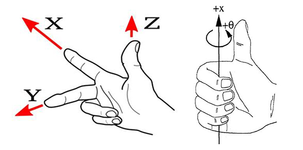
Standards exist in the machine tool industry for associating linear and rotary axes and defining positive move directions of all axes. Adhering to these standards removes uncertainty when anticipating how machine axes will move in response to motion commanded in part space. The positive move directions and the orientation of the axes in the Part coordinate system are defined per the right hand rule as shown to the right. The left hand image is for positive linear convention and the right hand image is for positive angular convention. |
 |
| TCP Machine Tool Standards | Rotation occurs about a part linear axis per the relationship shown in the figure to the right. When TCP is active, the A axis rotates the tool center point about the part X axis, the B axis rotates the tool center point about the part Y axis and the C axis rotates the tool center point about the Z axis. |
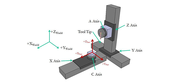 |
| Machine Configuration | To perform TCP kinematic calculations, the controller must know the locations of the tool, part and rotary axes and the configuration of the rotary axes. Offset Position Configuration A common approach to establishing machine configuration is to specify offsets between the points of rotation of the rotary axes and the location of the tool and the part. This configuration mode accommodates the input of coordinates based on their distances from the Part or Tool Tip they are connected to. Absolute Position Configuration Another common approach is using the absolute positions of all system elements based on their location in a “World” coordinate frame. |
|
| Acceleration Limiting | The CoordinatedAccelLimit parameter will stop or slow down path velocity for non-tangent linear moves. The DependentCoordinatedAccelLimit parameter will stop or slow down program velocity for non-tangent rotary axis moves. Note: The effect of changing speed on the machining process may prevent the use of Acceleration limiting in applications which require constant surface speed. |
|
| Commanded Velocity Filtering |
A low pass IIR filter (TrajectoryIIRFilter) or moving average FIR filter (TrajectoryFIRFilter) can be applied to the velocity command of the virtual and/or physical axes. The filter is applied continuously and will modify the program path by rounding all of the transitions between moves, even those that do not exhibit large accelerations. The positions of the linear servo axes are calculated from the virtual x/y/z axes and the servo rotary axis commanded positions. Similar filter settings should be applied to both virtual x/y/z and physical A/B/C axes to ensure consistent phasing of commanded position used to calculate the servo X/Y/Z positions. Note: Applying a filter to the servo rotary A/B/C axes and servo X/Y/Z axes will cause the servo X/Y/Z axes to lag behind the servo rotary axis position command. |
|
| Path Optimization | Lead on/lead off moves or “skywriting” is commonly used in X/Y applications to ensure the tool is only engaged in the material at constant speed. The calculation of lead moves or skywriting sequences is more complex on 3D shapes as the inserted path geometry cannot cause a collision between the part and the tool. Normally the process consists of a lead-off and lead-on move inserted between two nontangent features. The tool is turned off before the lead-off at constant surface speed. The path velocity decelerates to 0 during the lead off move. The controller moves to the start of the lead-on move, which is tangent to the next path segment and the system reaches constant speed during the lead-on move and enable the tool at the end of the lead-on move. |
Name |
Function |
Description |
|
| Path Optimization | Profile-Specific Path Optimization | Organize >1,000,000 drill locations with the shortest path distance in seconds. Organize for single FOV or with IFOV. | 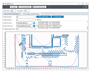 |
| Motion Optimization | Drive & Motor Parameter Optimization | Optimize AGV laser scan head hardware to execute 100% of moves at maximum performance within the user-defined settle window. Eliminate any delay for laser trigger and motion settle. | 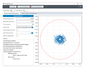 |
| Execution Framework | OptimalRapid Library & Program Execution | OptimalRapid is an AeroscriptPlus library that uses Path Optimization and Motion Optimization outputs to execute the list of points using a small, lightweight program that enables rapid iteration of different motion profiles and optimized parameters. Use it to iterate and obtain production scale performance quickly. | 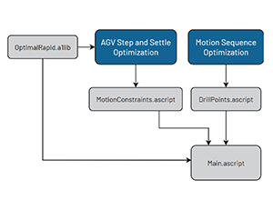 |
| API | .NET Dll | DrillOptimizer includes a Windows .exe for performing Path Optimization and Motion Optimization, plus a .NET Dll so machine builders can integrate its functionality into their custom machine HMI. |  |
Dimensions
Ordering Information
Filetype
| Option |
| Compiled AeroScript Library File |
File
| Option | Description |
| -F1 | Optical Alignment Algorithms, Compiled AeroScript Library File |
| -F2 | Tool Center Point Programming, Compiled AeroScript Library File |
| -F3 | Drill Optimizer, Windows Application, API & Compiled AeroScript Library File |
- To load and run AeroScriptPlus files on your controller, your Automation1-iSMC motion controller must be configured with the -AP1 option.