Automation1 XR3 Mehrachsiger Servoantrieb Rack
Ausgestattet mit einer Hochleistungs-Regelelektronik ist der XR3 der leistungsstärkste Mehrachsregler von Aerotech. Sowohl die Stromschleife als auch der Servoregelkreis werden digital geschlossen, um ein Höchstmaß an Positioniergenauigkeit und Wiederholbarkeit zu gewährleisten. Dank dieser Verarbeitungsfunktion kann der XR3 Schleifenschlussraten von bis zu 20 kHz bieten und sowohl digitale als auch analoge E/A-Verarbeitung, Datenerfassung, Prozesssteuerung und Encoder-Multiplikationsaufgaben in Echtzeit bewältigen.
Description
Specifications
Dimensions
Ordering Info
Downloads
Description
Description
Specifications
Dimensions
Ordering Info
Downloads
Description
Design-Merkmale
- Bestandteil der Automation1-Präzisions-Bewegungssteuerungsplattform von Aerotech
- Kompatibel mit A3200 Version 6.04 und neuer
- Plug-In PWM-, Linear- und Piezoverstärker
- Dedizierte Steuerkarte für jeden Verstärker
- Antrieb von Bürsten-, bürstenlosen, Schritt-, Schwingspulen- oder Piezomotoren
- Bis zu 30 A Spitzenausgangsstrom
- Integral Safe Torque Off (STO)
- Positionssynchronisierter Ausgang (PSO)
- Integrale Stromversorgungen
- HyperWire®-Lichtwellenleiter-Schnittstelle
- CE zugelassen, NRTL Sicherheitszertifizierung, EU 2015/863 RoHS 3 Richtlinie
Der XR3 ist ein leistungsstarkes, sechsachsiges Antriebsrack mit vor Ort austauschbaren, frontseitig montierten Verstärkern. Alle Versionen sind 3HE groß, rack-montierbar und kompatibel mit der Motion-Plattform Automation 3200.
Sehen Sie, wie Automation1 Servoantriebe die Positionsstabilität verbessern.
Zur Standardausstattung des XR3 gehören eine Bremsensteuerungslogik pro Achse, eine zusätzliche Encoder-Rückmeldung und eine analoge E/A-Erweiterung. Ebenfalls Standard sind 16 opto-isolierte Eingänge, 16 opto-isolierte Ausgänge, bis zu 12 Hochgeschwindigkeits-Differentialausgänge, 3 externe PSO-Sync-Eingänge, 3 TTL- oder isolierte PSO-Ausgänge, 1 opto-isolierter Datenerfassungseingang und 2 STO-Sense-Eingänge.
Der XR3 unterstützt Open-Loop-Steuerung, Standard-Rechteck-Encoder-Rückführung, analoge Eingangsrückführung und absolute Encoder-Rückführung.
Zu den Standardoptionen für den XR3 gehören drei verschiedene Stufen der integrierten Encoder-Multiplikation, einschließlich Optionen, die Dual-Loop-Encoder-Feedback unterstützen, Optionen für die Kühlung des Frequenzumrichters, Rack- oder Slide-Montage-Optionen und Mehrachsen-Positions-Synchronized-Output (PSO)-E/A für latenzarme, positionsbasierte Prozesssteuerung.
Außerdem ist eine Vielzahl von Erweiterungen der PSO-Basisfunktionalität verfügbar. Verfolgen Sie bis zu drei Encoder in Echtzeit mit dreiachsigem PSO oder erweitern Sie die PSO-Funktionalität auf kinematische Anordnungen durch die Verwendung von Aerotechs Part-Speed-PSO-Funktion.
Der XR3 verwendet Steckverstärker, die sowohl lineare als auch PWM-Topologien unterstützen, um bürstenlose, bürstenbehaftete oder Schrittmotortypen mit einer Betriebsspannung von bis zu 320 VDC und einem Spitzenstrom von 30 A zu steuern. Der XR3 enthält zwei konfigurierbare Stromversorgungsabschnitte zur Unterstützung einer Vielzahl von Motoren mit unterschiedlichen Betriebsspannungen. Wenn nur eine Motorspannung benötigt wird, werden die Stromversorgungsabschnitte miteinander verbunden, um eine noch höhere Leistung zu erreichen. Der XR3 unterstützt bis zu drei Achsen mit positionssynchronisiertem Ausgang (PSO) zur präzisen Synchronisierung externer Geräte, Überspannungs-Shunt-Controller und externe Lüfter für den Betrieb mit hoher Leistung.
>
Description |
XR3 |
| Motion Bus | HyperWire |
| Number of Amplifiers | 1 to 6 (Each amplifier requires a controller card in order to be used). |
| Number of Controller Cards | 1 to 6 |
| Encoder Inputs | 2 per controller card. |
| Motor Style | Brush, Brushless, Stepper, Voice Coil |
| Input Current -VL1 | 120 VAC, 10 A Maximum |
| Input Current -VL2 | 240 VAC, 5 A Maximum |
| Input Current -VL3 | 100 VAC, 10 A Maximum |
| Input Current -VL4 | 200 VAC, 5 A Maximum |
| Bus Voltage Options -VB1 | ±10 VDC (200 W Power Supply), bipolar |
| Bus Voltage Options -VB2 | ±20 VDC (200 W Power Supply), bipolar |
| Bus Voltage Options -VB3 | ±30 VDC (200 W Power Supply), bipolar |
| Bus Voltage Options -VB4 | ±40 VDC (300 W Power Supply), bipolar |
| Bus Voltage Options -VB5 | ±80 VDC (300 W Power Supply), bipolar |
| Bus Voltage Options -VB7 | +160 VDC, unipolar |
| Bus Voltage Options -VB8 | +320 VDC, unipolar |
| AC Power Input | AC input (Switch Selectable): AC Hi, AC Lo, Earth Ground (⏚), ● 100 VAC (90-110 VAC, 50/60 Hz) ● 120 VAC (108-132 VAC, 50/60 Hz) ● 200 VAC (180-220 VAC, 50/60 Hz) ● 240 VAC (216-264 VAC, 50/60 Hz) Note: If the XR3 contains an offline Bus power supply, the AC Input will be limited to one AC input range. |
| Inrush Current | 32 Apk |
| Auxiliary Power Outputs | +5 V provided on all axis feedback connectors for encoder, Hall, and limit power. +5 V provided on I/O connectors |
| Protection | The AC power cord serves as the mains breaker and provides 10 A, Supplemental Protection only. Internal Bus supply fusing. Amplifier Output short circuit protection. Peak and RMS over current limit. Over Temperature shutdown. Bus supply inrush current limit during initial power-on. |
| Internal Shunt Resistor | 40 W Continuous; 400 W Peak (5 seconds) |
| Safe Torque Off (STO) | Yes |
| Digital I/O | 16x digital inputs, optically isolated 16x digital outputs, optically isolated |
| Position Synchronized Output (PSO) | 3x PSO isolated outputs 3x PSO TTL outputs 3x PSO synchronization inputs |
| Data Acquisition | 1x high-speed input (50 nsec latency) |
| Sync Ports | 2 |
| Operating Temperature | 0 to 50°C |
| Storage Temperature | -30 to 85°C |
| Weight | 25 kg. (55 lb.) |
-CTN |
-CT1 |
-CT2 |
-CT4 |
|
| Current Loop Update Rate | 20 kHz | 20 kHz | 20 kHz | 20 kHz |
| Servo Loop Update Rate | 20 kHz | 20 kHz | 20 kHz | 20 kHz |
| High-Speed Outputs | 2x high-speed RS-422 differential outputs (per controller card) | 2x high-speed RS-422 differential outputs (per controller card) | 2x high-speed RS-422 differential outputs (per controller card) | 2x high-speed RS-422 differential outputs (per controller card) |
| 25-Pin Motor Feedback Connector(1) |
High-speed differential inputs (encoder sin, cos and marker; absolute clk and data) CW and CCW limits Hall effect sensor inputs (A, B, and C) Analog motor temperature input (accepts digital) Brake output |
High-speed differential inputs (encoder sin, cos and marker; absolute clk and data) CW and CCW limits Hall effect sensor inputs (A, B, and C) Analog motor temperature input (accepts digital) Brake output |
High-speed differential inputs (encoder sin, cos and marker; absolute clk and data) CW and CCW limits Hall effect sensor inputs (A, B, and C) Analog motor temperature input (accepts digital) Brake output |
High-speed differential inputs (encoder sin, cos and marker; absolute clk and data) CW and CCW limits Hall effect sensor inputs (A, B, and C) Analog motor temperature input (accepts digital) Brake output |
| 9-Pin Aux Encoder Feedback Connector | High-speed differential inputs (encoder sin, cos and marker; absolute clk and data) |
High-speed differential inputs (encoder sin, cos and marker; absolute clk and data) |
High-speed differential inputs (encoder sin, cos and marker; absolute clk and data) |
High-speed differential inputs (encoder sin, cos and marker; absolute clk and data) |
| 15-Pin Analog I/O Connector | 2x 16-bit differential ±10 V analog input 2x 16-bit single-ended ±10 V analog output Joystick: Button A, Button B, and Interlock |
2x 16-bit differential ±10 V analog input 2x 16-bit single-ended ±10 V analog output Joystick: Button A, Button B, and Interlock |
2x 16-bit differential ±10 V analog input 2x 16-bit single-ended ±10 V analog output Joystick: Button A, Button B, and Interlock |
2x 16-bit differential ±10 V analog input 2x 16-bit single-ended ±10 V analog output Joystick: Button A, Button B, and Interlock |
| 5-Pin How Powered Motor Connector(1) |
Brushless Phase A, B and C connections or DC Brush +/- connections or Stepper (2 phases with return) |
Brushless Phase A, B and C connections or DC Brush +/- connections or Stepper (2 phases with return) |
Brushless Phase A, B and C connections or DC Brush +/- connections or Stepper (2 phases with return) |
Brushless Phase A, B and C connections or DC Brush +/- connections or Stepper (2 phases with return) |
| Primary encoder input specifications |
Square-wave Encoder 40 million counts-per-second input Absolute Encoder Yes Sine-wave Encoder n/a |
Square-wave Encoder 40 million counts-per-second input Absolute Encoder Yes Sine-wave Encoder 2 MHz / 450 kHz (bandwidth selectable) input with up to 16,384 multiplication |
Square-wave Encoder 40 million counts-per-second input Absolute Encoder Yes Sine-wave Encoder 2 MHz / 450 kHz (bandwidth selectable) input with up to 65,536 multiplication |
Square-wave Encoder 40 million counts-per-second input Absolute Encoder Yes Sine-wave Encoder 2 MHz / 450 kHz (bandwidth selectable) input with up to 65,536 multiplication |
| Auxiliary encoder input specifications |
Square-wave Encoder 40 million counts-per-second input Absolute Encoder Yes Sine-wave Encoder n/a |
Square-wave Encoder 40 million counts-per-second input Absolute Encoder Yes Sine-wave Encoder n/a |
Square-wave Encoder 40 million counts-per-second input Absolute Encoder Yes Sine-wave Encoder n/a |
Square-wave Encoder 40 million counts-per-second input Absolute Encoder Yes Sine-wave Encoder 2 MHz / 450 kHz (bandwidth selectable) input with up to 65,536 multiplication |
| Can Output Multiplied Encoder | n/a | No | Yes | Yes |
Feature |
XSP3-10 |
XSP3-20 |
XSP3-30 |
| Option Code | -P1 | -P2 | -P3 |
| Peak Motor Output Current (2 sec)(1)(2) | 10 Apk | 20 Apk | 30 Apk |
| Continuous Current (2) | 5 A | 10 A | 10 A |
| Maximum Bus Voltage | 320 VDC | 320 VDC | 320 VDC |
| Maximum Power Amplifier Bandwidth(3) | 2 kHz | 2 kHz | 2 kHz |
| PWM Switching Frequency | 20 kHz | 20 kHz | 20 kHz |
| Minimum Load Inductance | 0.1 mH @ 160 VDC bus (1.0 mH @320 VDC bus) | 0.1 mH @ 160 VDC bus (1.0 mH @320 VDC bus) | 0.1 mH @ 160 VDC bus (1.0 mH @320 VDC bus) |
| Heat Sink Temperature (maximum allowable) | 75°C (All Amplifiers) | 75°C (All Amplifiers) | 75°C (All Amplifiers) |
Feature |
XSL3-10-40(5)(6)(7)(8) |
| Option Code | -L1 |
| Continuous Output Current, ±40V bus (Apk)(2)(3)(4) | 1.5 A | 2.0 A |
| Peak Current (Apk) | 10 Apk(1) |
| Maximum Continuous Total Power Dissipation(3)(4) | 120 W | 160 W |
| Peak Amplifier Power Dissipation per phase | 400 W |
| Effective Heatsink Thermal Resistance | 0.42ᴼC/W | 0.31ᴼC/W |
| Maximum Transistor Temperature | 75ᴼC |
| Time to reach maximum temperature at maximum continuous power | 20 minutes |
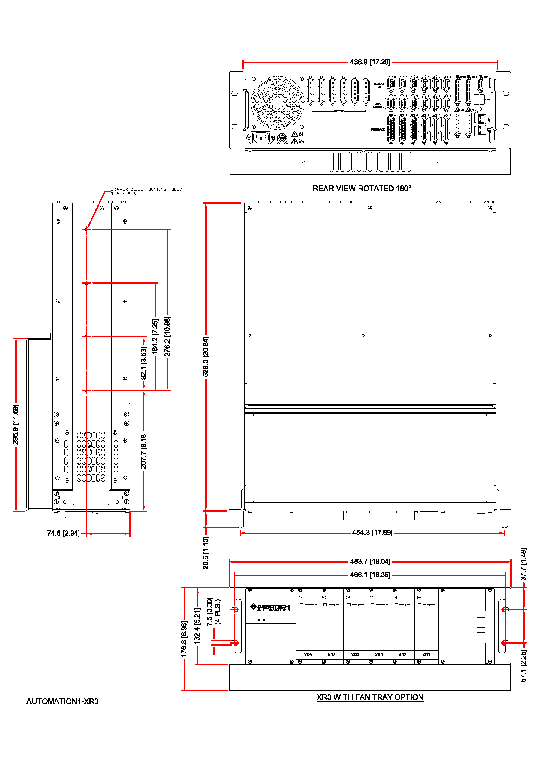
Dimensions
XR3, Rack Mounted

XR3, Rack Mounted with Drawer Slides
Ordering Information
Automation1 XR3
| Option | Description |
| Automation1 XR3 | Automation1 XR3 - 3U, 19” Multi-Axis Servo Drive Rack with Motion Controller |
Line Voltage
| Option | Description |
| -VL1 | 120 VAC input |
| -VL2 | 240 VAC input |
| -VL3 | 100 VAC input |
| -VL4 | 200/208 VAC input |
- Line voltages VL2 and VL4 are not available with bus voltage selection VB7. Line voltages VL1 and VL3 are not available with bus voltage VB8.
Bus Voltage 1
| Option | Description |
| -VB1 | ±10 VDC (200 W power supply), bipolar |
| -VB2 | ±20 VDC (200 W power supply), bipolar |
| -VB3 | ±30 VDC (200 W power supply), bipolar |
| -VB4 | ±40 VDC (300 W power supply), bipolar |
| -VB5 | ±80 VDC (300 W power supply), bipolar |
| -VB7 | 160 VDC unipolar |
| -VB8 | 320 VDC unipolar |
- Bus voltages options are limited based upon other configuration selections.
Bus Voltage 2
| Option | Description |
| -VB0 | Not Wired |
| -VB1 | ±10 VDC (200 W power supply), bipolar |
| -VB2 | ±20 VDC (200 W power supply), bipolar |
| -VB3 | ±30 VDC (200 W power supply), bipolar |
| -VB4 | ±40 VDC (300 W power supply), bipolar |
| -VB5 | ±80 VDC (300 W power supply), bipolar |
| -VB7 | 160 VDC unipolar |
| -VB8 | 320 VDC unipolar |
- Bus voltages options are limited based upon other configuration selections.
Split Bus
| Option | Description |
| -SB0 | Axis 1-6 bus voltage 1 (no split) |
| -SB1 | Axis 1 bus voltage 1, axis 2-6 bus voltage 2 |
| -SB2 | Axis 1-2 bus voltage 1, axis 3-6 bus voltage 2 |
| -SB3 | Axis 1-3 bus voltage 1, axis 4-6 bus voltage 2 |
| -SB4 | Axis 1-4 bus voltage 1, axis 5-6 bus voltage 2 |
| -SB5 | Axis 1-5 bus voltage 1, axis 6 bus voltage 2 |
Controller Cards
| Option | Description |
| -CT0 | No controller card |
| -CTN | Controller card without Multiplier |
| -CT1 | Controller card with MX1 Multiplier |
| -CT2 | Controller card with MX2 Multiplier |
| -CT4 | Controller card with MX4 Multiplier |
Amplifier Cards
| Option | Description |
| -P0 | No amplifier |
| -P1 | XSP3-10 amplifier |
| -P2 | XSP3-20 amplifier |
| -P3 | XSP3-30 amplifier |
| -L1 | XSL3-10-40 amplifier |
- Linear amplifier option L1 requires bus voltage VB1, VB2, VB2 or VB4 and requires cooling option C1 or C2.
Cooling
| Option | Description |
| -C0 | Built-in fan pulls cooling air from left side |
| -C1 | Perforated covers above and below amp |
| -C2 | 1U-high fan tray for cooling |
- For C1 option, refer to the hardware manual for the external cooling requirements.
Line Cord
| Option | Description |
| -LC0 | No line cord |
| -LC1 | USA 120 VAC compatible line cord |
| -LC2 | USA 240 VAC compatible line cord |
| -LC3 | German compatible line cord |
| -LC4 | UK compatible line cord |
| -LC5 | Israel compatible line cord |
| -LC6 | India compatible line cord |
| -LC7 | Australia compatible line cord |
PSO
| Option | Description |
| -PSO1 | One-axis PSO (default) |
| -PSO2 | Two-axis PSO |
| -PSO3 | Three-axis PSO |
- Up to 3 independent PSO outputs can be programmed and used. Each independent PSO output requires an independent controller card
Internal Shunt (Optional)
| Option | Description |
| -SI1 | Internal shunt, first bus |
| -SI2 | Internal shunt, second bus |
| -SI3 | Internal shunt, first and second bus |
- Internal shunts not available for all voltage bus options.
Integration (Required)
Aerotech offers both standard and custom integration services to help you get your system fully operational as quickly as possible. The following standard integration options are available for this system. Please consult Aerotech if you are unsure what level of integration is required, or if you desire custom integration support with your system.
| Option | Description |
| -TAS | Integration - Test as system Testing, integration, and documentation of a group of components as a complete system that will be used together (ex: drive, controller, and stage). This includes parameter file generation, system tuning, and documentation of the system configuration. |
| -TAC | Integration - Test as components Testing and integration of individual items as discrete components that ship together. This is typically used for spare parts, replacement parts, or items that will not be used together. These components may or may not be part of a larger system. |